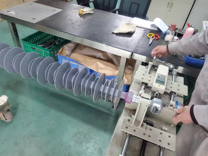
Verification of the loacking system of insulator
07-04-2022
The load is gradually increased until the locking device moves to the coupling position. The operation from the locking to the coupling position shall be carried out three times in succession. The load F which causes the locking device to move from the locking to the as shown in the coupling position is noted for each operation. After this, a toad Fmax as show in the acceptance criteria below, shall be applied without causing complete removal of the locking device from the socket.
Acceptance criteria for the operation test
The values of the load F for three operations shall be lie between the values of Fmin and Fmax given below:
| IEC Standard Coupling Size | Spilt Pins | W clips | ||
| Fmin | Fmax | Fmin | Fmax | |
| 11 | 30 N | 300 N | 25 N | 250 N |
| 16A, 16B, 20, 24 | 50 N | 500 N | 25 N | 250 N |